Практический обзор 3D-принтера Rostock BI V1
Содержание:
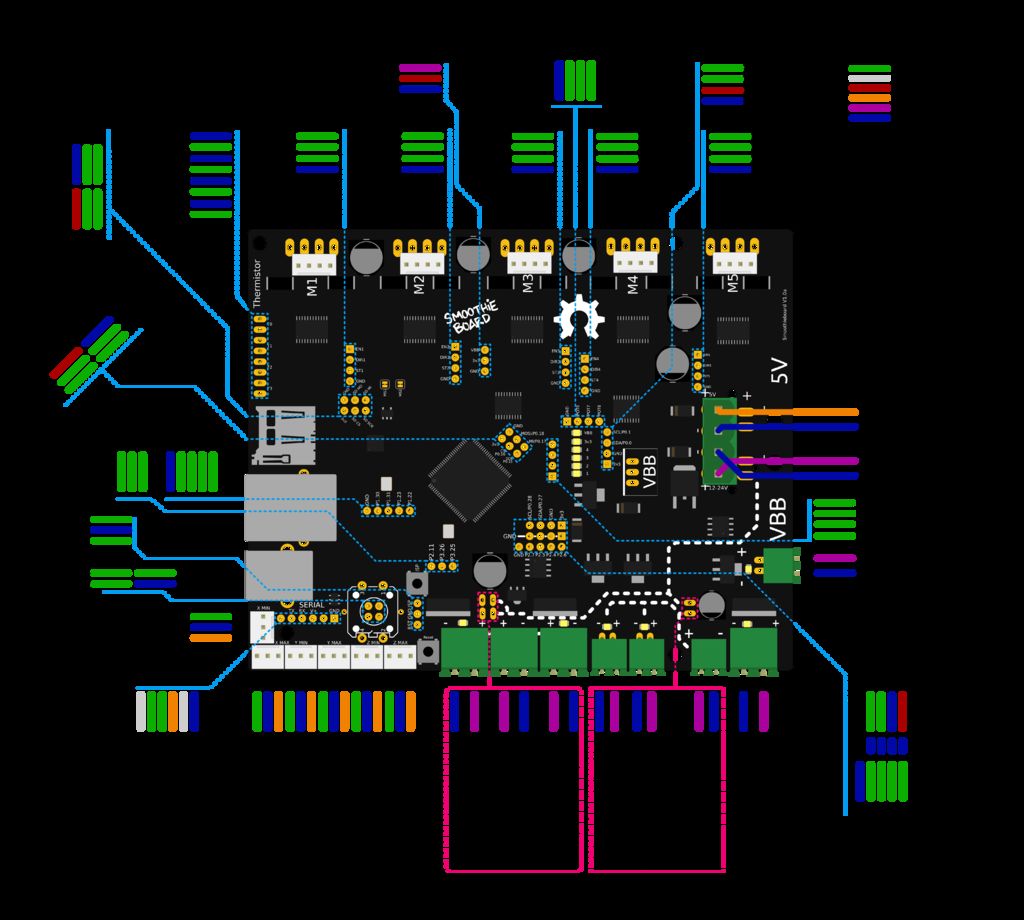
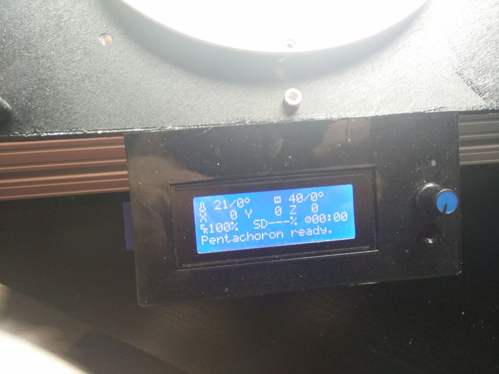
Step 8 Setting Up Smoothieware

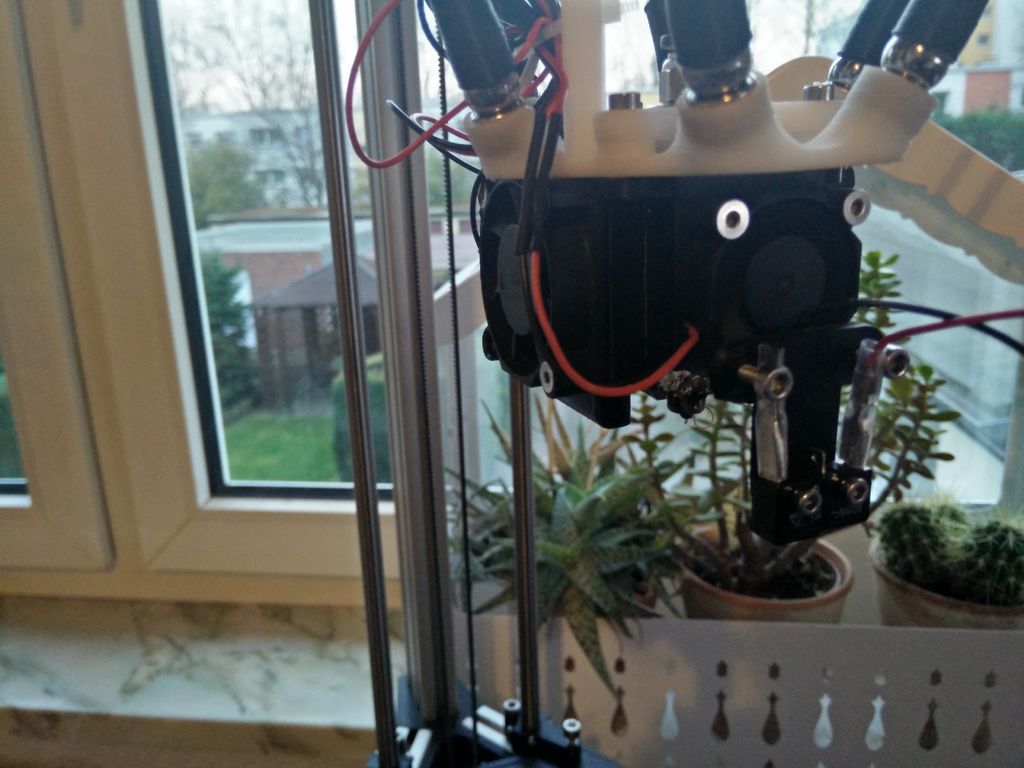
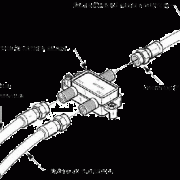
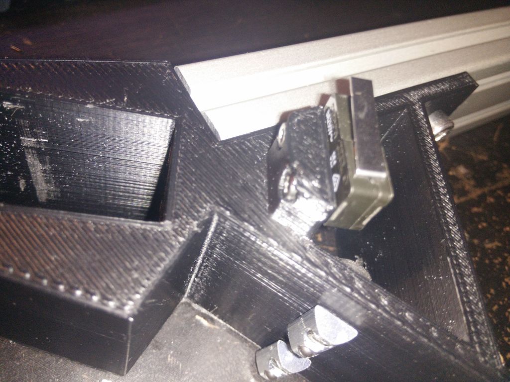
I uploaded my config file for you to download. If you use it, it should work fine. A z-probe is setup there — but you’ll only need one for auto calibration. The temporarly attached endstop for calibration is shown in the picture.
Always remember: when you change a setting in the config or config_override-file you have to reset the smoothieboard. You can to so by using the hardwar-reset-button on the board or issue «reset» through pronterface.
If you have any problems you can consult the documentatiion for smoothieware.
Auto Delta Calibration
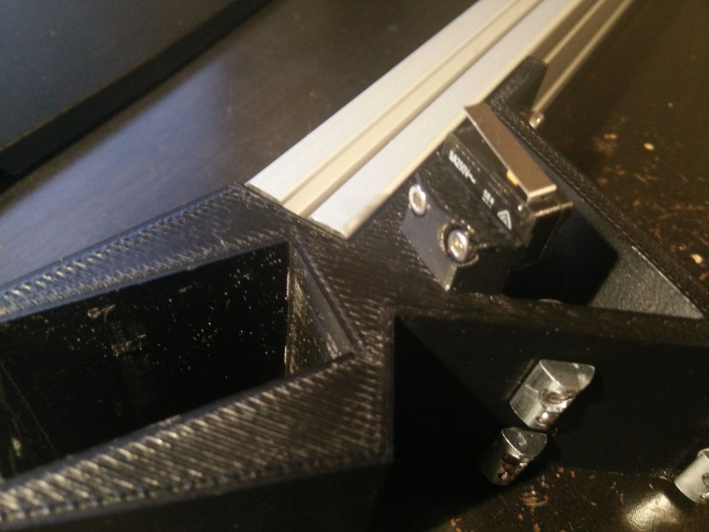
Auto Delta Calibration in smoothieware is pretty straight forward. First plug the probe into the z-min endstop pins on your board. Then install the temporarly probe on the effector.
Go to your firmware and set your «gamma_max» to about 20 mm less then your build height — so you avoid that your probe crashes into the buildplate. Then connect to the board via usa (using pronterface) and issue the «reset» command — the smoothieware will reboot and activate the values from the config-file.
Then issue the G32 command. The Auto Calibration will start and calibrate your printer. For this, the probe will probe 4 points (each tower + center) several times.
After the probing is completed use M500 to store the values. Reset the smoothiboard once again to activate the values.
Then open the «config_override» file on your smoothieboard. I had the problem, that it stored my «gamma_max» value so I couldn’t change it. Whenever you change a value in the config-file, make sure, this value doesn’t get overwritten by the config_override. If something is in the config_override, you don’t want there, simply delte these lines.
z-Height Calibration
Z-Height Calibration is straihgt forward as well — first remove the probe. Just use a number whichs is bigger than your expected build height for the «gamma_max»-value (Make sure, this values does not get overwritten by the config_override).Then drive your hotend down to your heated bed slowly until it graps your paper. To get your z-height just subtract the distance you have done from the distance you have set in your firmwarwe.
Delta Bed Leveling
At last you have to level your bed. For this you have to turn the screws in the top of the carriage. If you tighten them, the distance between nozzle is raised, if you loosen them, the nozzle is lowered.
You have to calibrate the nozzle on each tower, calibration points are:
G1 X-78 Y-45 Z0
G1 X78 Y-45 Z0
G1 X0 Y90 Z0
Dimensional Accuracy
At last you have to tune your dimensional accuracy. This is mostly dependend on the arm length. You can find a good guide here:
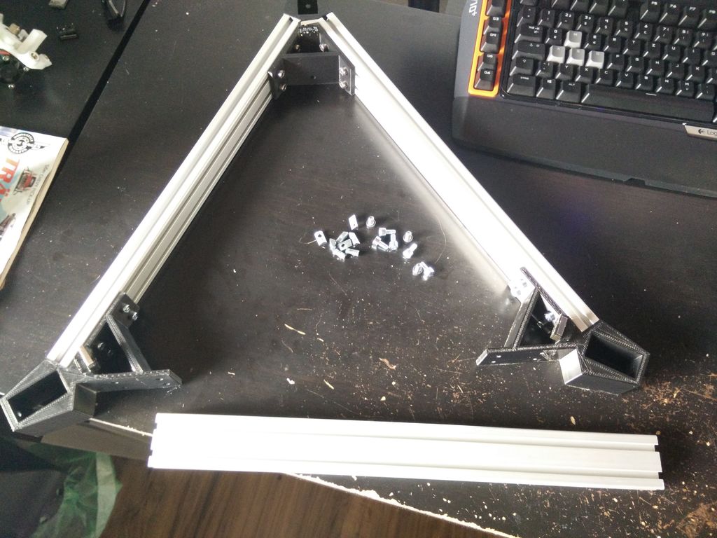
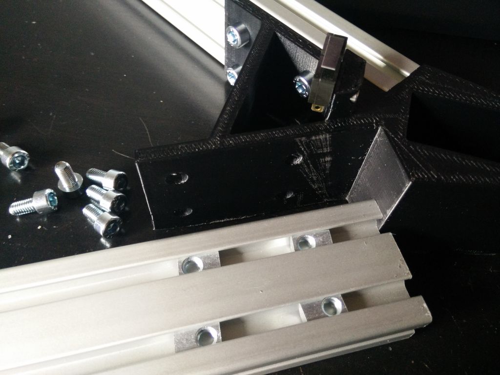
Step 4 Lower Frame Assembly
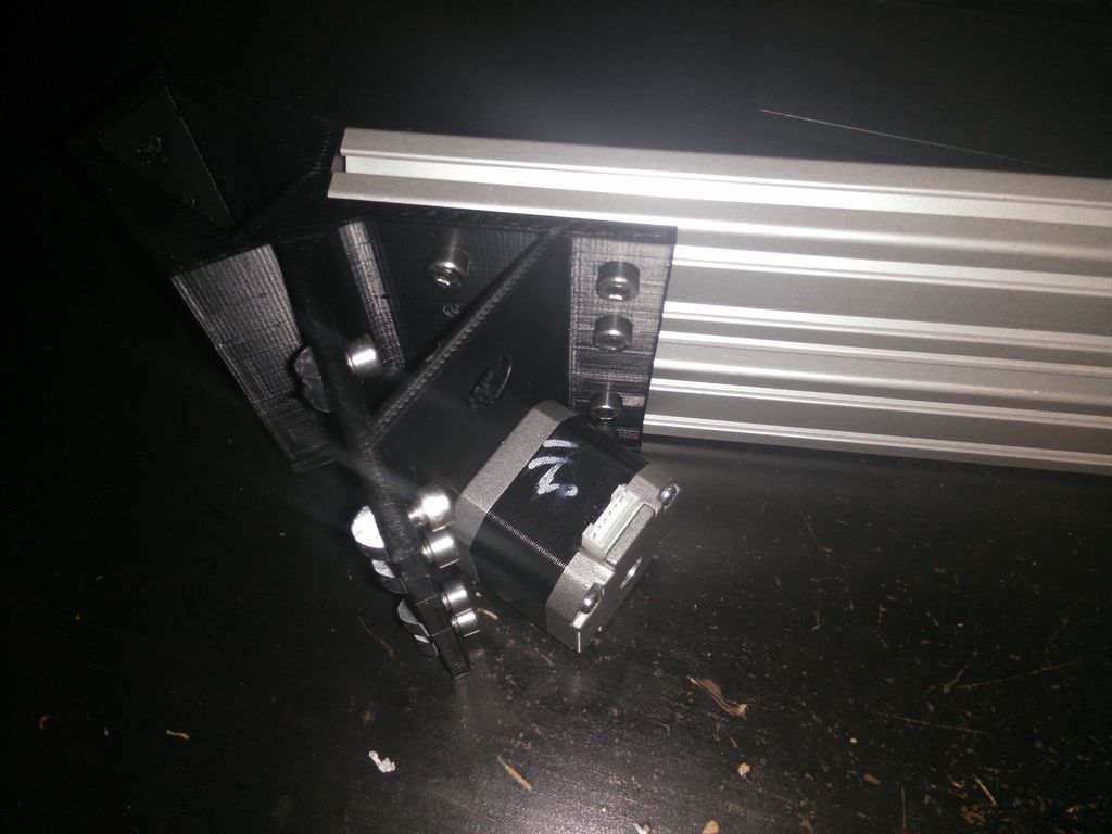


Lower frame
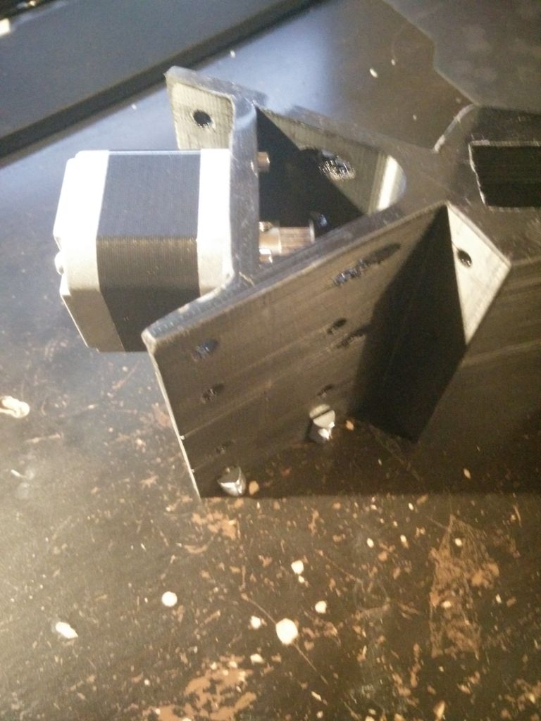
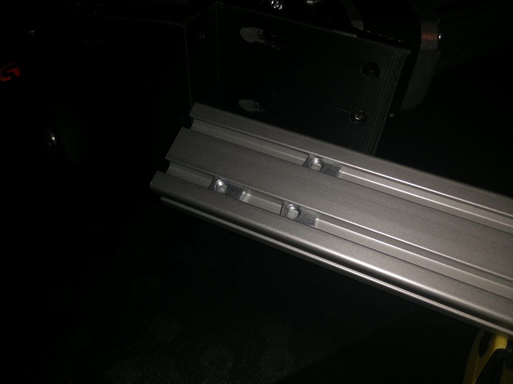
First install the Nema 17 Motor using the M3x10 screws. Then insert the M5x10 screws and T-Nuts in 2 of the 3 printed «bottom corner» parts and fit them together with the 390mm long 4020 aluminium extrusion. For the last side of the T-slot nuts into the aluminium extrusion, measured where they should be and fittet the last 2 4020 aluminium extrusion profiles.
Befor continuing the assembly us the assembled lower frame to draw out the contours of the plate, on which the PSU, micro controller and heated bed will be mounted. For the basic shape put the assembled lower frame onto a piece of plywood, drew the outline and cut it out. Do not drill any holes to mount the plate to the frame yet! To drill out the mounting holes for the PSU just put the PSU on your scanner and copy the bottom of it. I already have a mounting solution for my Smoothiboard — but tracing out the mounting holes for your electronics should not be a problem.
To get the spacing for the PCB heated bed right draw the center verticals and place the PCB on top. To get the parts mounted as easy as possible install the heated bed spacers first (to your plywood plate). After this you can install your PSU and your electronics. As a spacer for the PSU I simply used some Nylon washers.At last: put in the screws to mount the vertical 4020 extrusion profiles for the final frame assembly.
You can install the electronics and now or later — what ever floats your boat. I recommend to install them later, so you don’t damage them by (man) handling the plate while assembling.
Step 3 Upper Frame Assembly
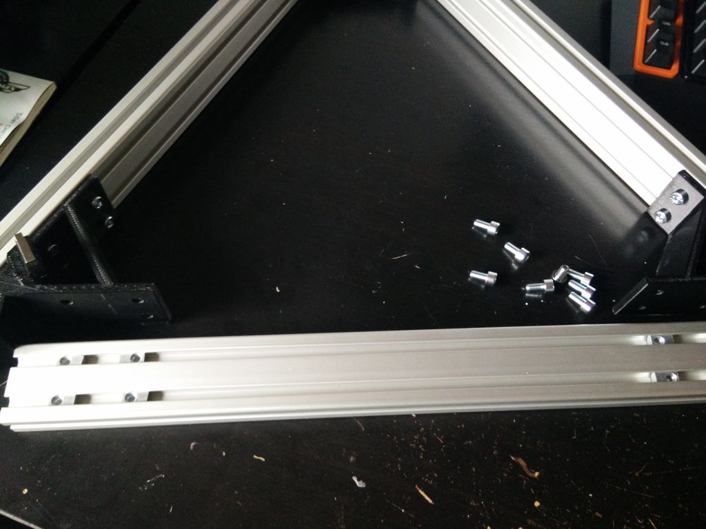
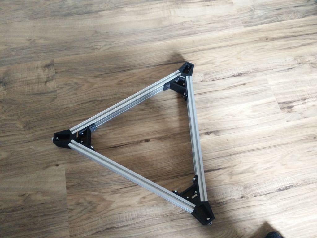
Upper frame
Take the three «upper corner» printed parts and insert the 10 M5x8 screws and T-Nuts. You can also mount the GT2 deflection pulleys using the 5x38mm steel rod (you may also use a M5x40 screw) and the endstops using the M2.5×10 screws. The holes in my endstops were tight enough (that’s what she said) to hold them in place just using screws without nuts. If you have problems holding them in place just use M2.5×12 screws and M2.5 nuts instead. Be aware: after completly assembling the frame the screws to mount the endstop will not be reachable.
Build the first to sides of the triangle and install all «top corner» parts. Lay down the last side of the 4020 extrusion next to where they should go and measured (eyeballed) where the T-slot nuts have to go. Then put everything together. At last I put in the screws to attach the upper frame to the vertical 4020 extrusions.
Характеристики дельта-принтера Rostock BI V1
- Диаметр нити: 1,75 мм;
- Вид нити: PLA, Laywoo-D3. Нейлон и ABS доступны после апгрейда;
- Габаритный размер: 380 мм х 330 мм х 580 мм;
- Рабочий объем: 170 мм диаметр, 155 мм высота, цилиндрическая область печати;
- Максимальная скорость печати: 200 мм/с;
- Минимальная толщина слоя: 100 мкм;
- Программное обеспечение: с открытым кодом;
- Другие особенности: кроватка с подогревом;
- Цена: $450 – DIY-kit или $699 – в собранном виде.
Одной из главных причин выбора этого принтера была его невысокая цена за полностью собранную модель.
Rostock использует экструдер Боуден, который монтируется на раму; это уменьшает массу на платформе, увеличивает скорость и точность печати. Принтер использует программное обеспечение Repetier и готовые настройки предназначенные для генерации G-кода в slic3r. На начальном этапе печати они использовались как есть, и результаты были достаточно хорошими. Однако возникли проблемы с печатью напряженных изделий, которые удалось разрешить после обращения к производителю.
После выяснения всех вопросов были выбраны объекты для тестирования, и вот результаты:
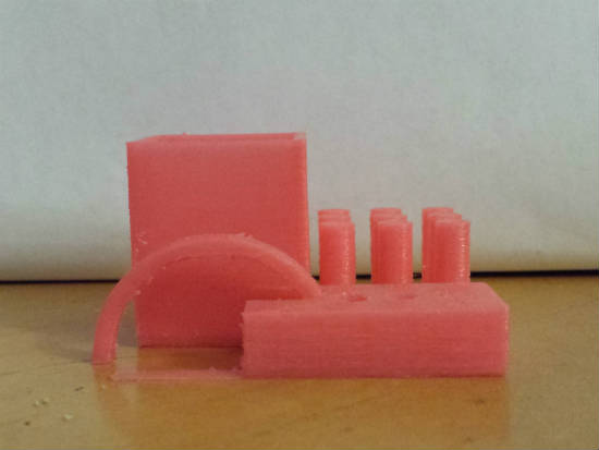
Первая тестовая модель была напечатана с разрешением 150 мкм при умеренной скорости 40 мм/с. На фотографии изделие без какой-либо обработки сразу после печати. Модель была напечатана без использования поддержки, так что получившуюся арку можно считать большим достижением. Единственной проблемой являются грубоватые углы, что можно было улучшить за счет усиления втягивания материала. Это была первая проверка, и оптимальный режим еще не был найден.
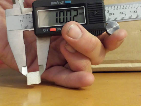
Тестовая модель на проверку точности размеров. У данного куба должна быть толщина равная 10 миллиметров. Результат достаточно близок, погрешность составила 20 мкм.
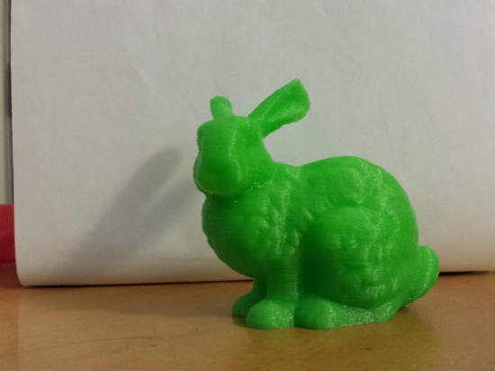
Стэнфордский кролик был напечатан с разрешением в 100 микрон и вышел почти безупречно. Заодно был проверен пластик зеленого цвета, получилось очень мило.
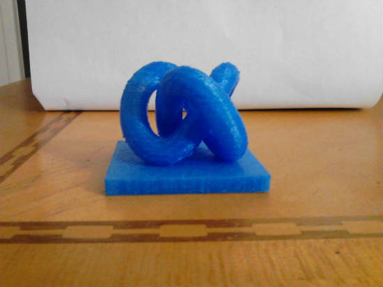
3D-узел был рекомендован для проверки втягивания материала экструдером при печати. Он вполне удался с разрешением 200 мкм. При печати было два свеса пластика в середине, но ведь всего только пара, т.е. результат весьма неплох.
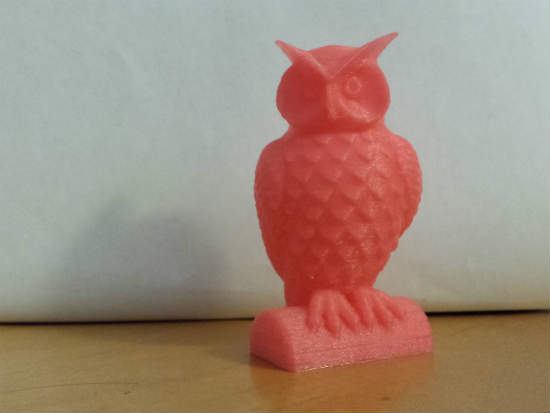
Статуэтка Совы выглядит простой, но на самом деле на ней интенсивно проверяется свисание материала. Есть некоторые незначительные недостатки на нижних перьях и клюве. Отпечатано с разрешением 150 мкм в 60% масштаба от оригинала.
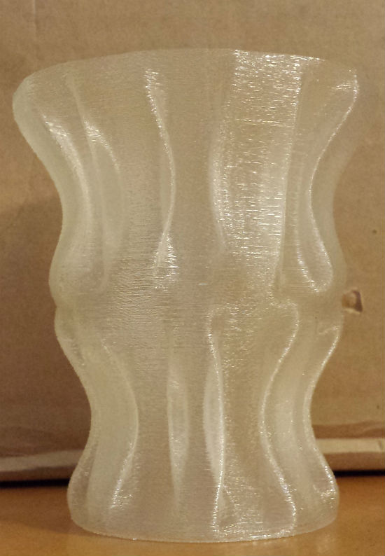
Вазы являются одним из самых популярных объектов для печати. Для теста использовался дизайн ленточной ленты вазы с разрешением 250 микрон из slic3r. Процесс печати в полном размере занял полтора часа.
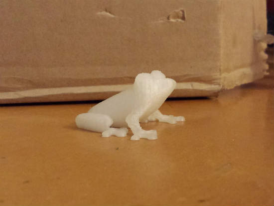
Для проверки возможностей Rostock BI V1 была напечатана древесная лягушка с разрешением 70 мкм (напоминаем, по заявлению производителя наилучшее разрешение составляет 100 мкм). Данная модель также распечатывалась в начале, до внесения всех корректировок в настройки, поэтому, возможно, могла получиться и лучше. Но в целом изделие получилось весьма гладким, правда с несколькими проблемами на ноге.
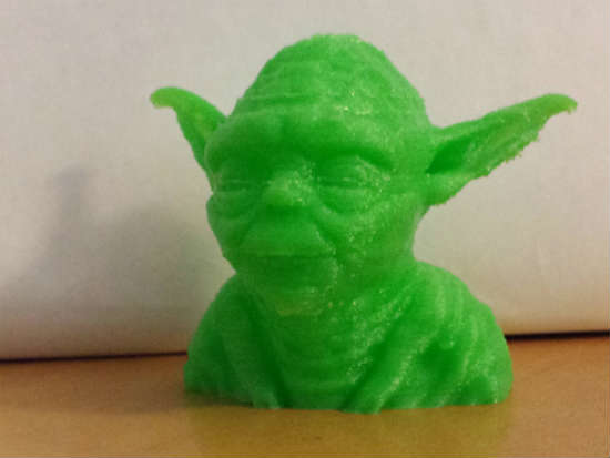
Ни один обзор 3D-принтера не будет полным без Йоды. Это серьезное испытание навеса для подбородка и ушей, и Rostock BI V1 прилично справился на разрешении 150 мкм.
В целом результаты положительные, и принтер заслуживает хороших отзывов:
- Изделие приклеивается к стеклянной кроватке с подогревом и легко отрывается;
- Печать довольно быстрая;
- После небольших корректировок настроек практически каждая печать стала успешной.
Но имеются у него и недостатки:
- Небольшой рабочий объем;
- Экструдер Боуден требует доработки, т.к. нить находится под значительным давлением и втягивание отрабатывается недостаточно хорошо;
- При некоторых условиях вентилятор охлаждения может попасть под экструдер;
- При парковке печатающей головки она может выйти за пределы рабочей области, т.к. нет никаких ограничителей.
Отзыв дан для модели Rostock BI V1, которая уже распродана. Изготовитель теперь работает над версией V2. Она будет совершенствоваться в нескольких направлениях, но больше всего радует обещанное автоматическое выравнивание.
Step 6 Effector Assembly, Electronics and Wiring

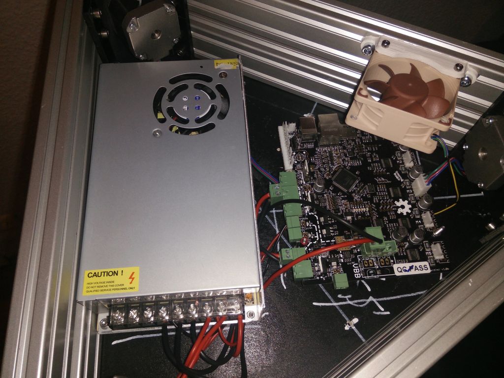
Electronics
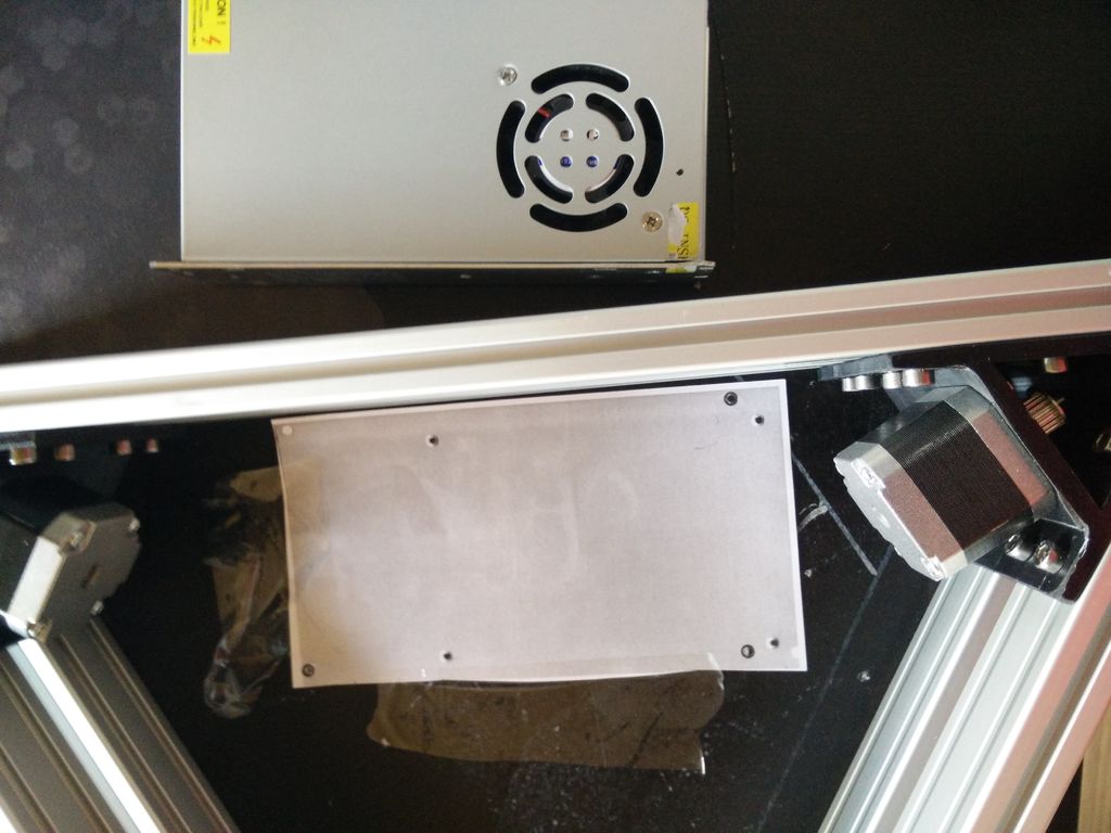
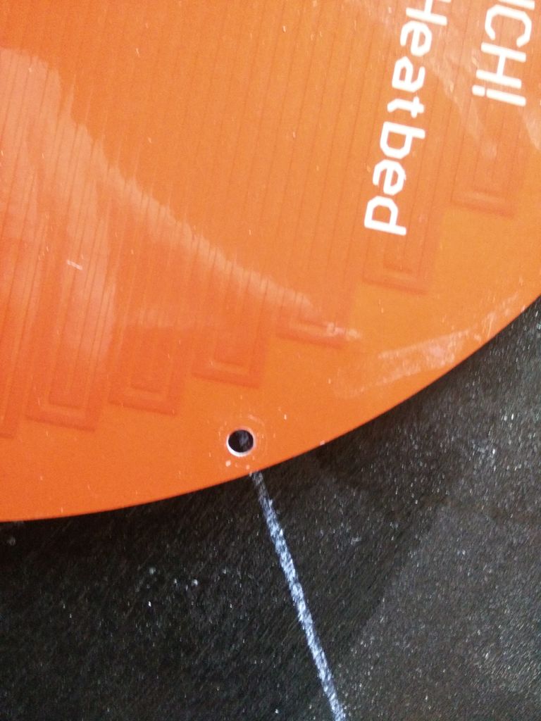
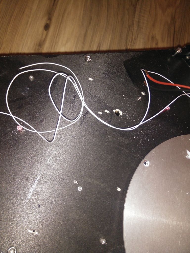
Now you can start to installe the electronics. It is important, that you mount the spacers for the heated bed first! Then you can mount spacers for the PSU, install the PSU and add your electronics. You can install your heated bed now as well. I drilled an additional (bigger) hole near the center of the heated bed to route the cables thorugh.
The cables for the endstops where routed through the center of the vertical aluminium extrusion profiles — I also routet the cables for the extruder motor through this holes.
Wire your parts correctly and you’ll hopefully not fry your electronics.
Effector
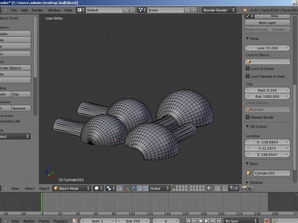
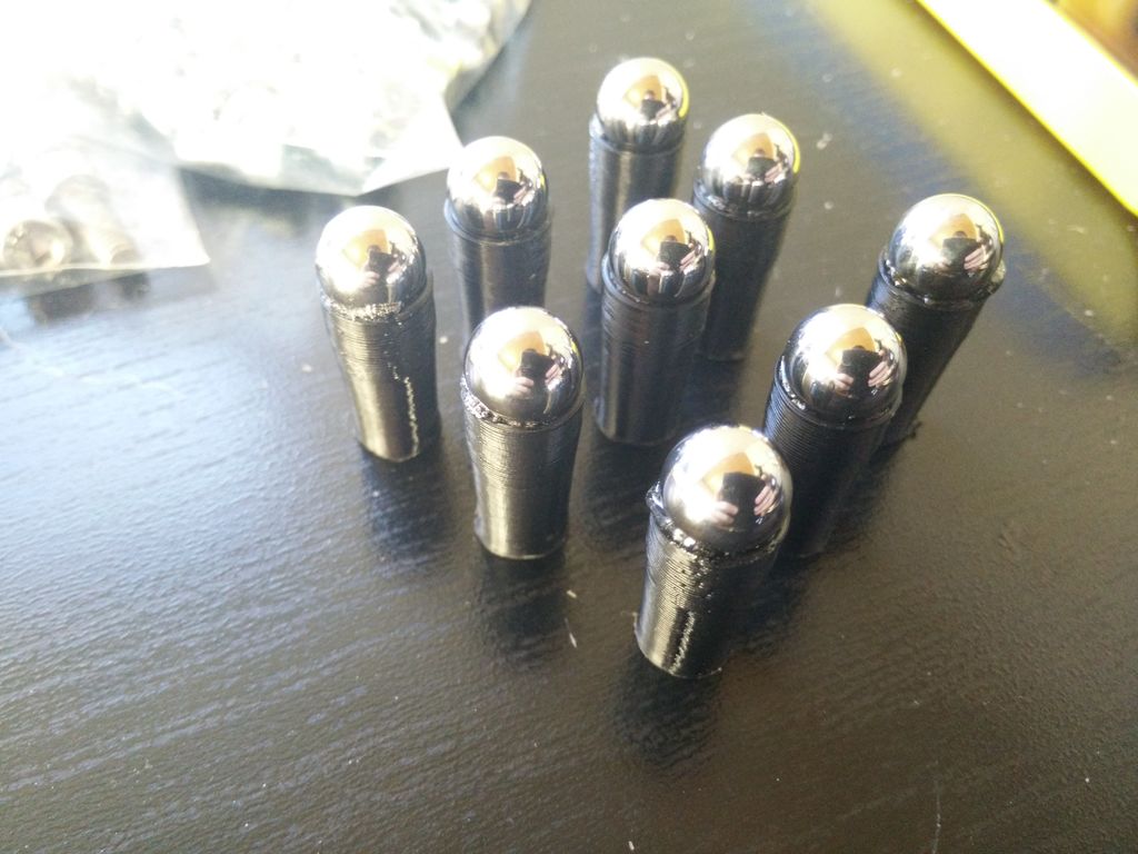
Then start to assemble the rods connecting the carrier to the effector. Glue in the 10mm ball bearing balls into the «rod end» — you need to build 12 of these. Then glue them onto the carbon rods (don’t use quick drying glue) — make shure all pieces are exactly the same length. To do so you can clamp them between two pieces of wood and adjust the length as needed. Now you can start assembling the effector.
You can now put your effector and rods into the printer and wire everything up.
Step 1 Parts List
- 3x1000mm 4020 aluminium extrusion
- 9x390mm 4020 aluminium extrusion
- 1x200mm (approx.) 4020 aluminium extrusion (spool holder)
- 1x piece of plywood (or other material you’ll mount your heated bed and electronics to, at least 390x340mm)
- 6x steel rod, d=10mm, l = 865 mm
- 6x Igus lineare bearings (RJ4JP-01-10)
- 6x carbon rod 6x4mm, l = 300 mm
- 3x GT2 pulley 3x GT2 deflection pulley
- 3x 5×38(mm) steel rod (for GT2 deflection pulley)
- 3x GT2 belt (about 6m, I ordered 10m)
- 12x 10mm x 3mm round magnets
- 12x 10mm x 3mm round magnets with sink
- 12x 10mm ball bearing ball
- 1x bowden tube, about 500-700mm
Screws:
- 90x T-Slot Nuts (M5)
- 90x M5x10 (for the frame corners)
- 45x M3x12 (for rod holder, effector and carriage)
- 12x M3x10 (for Nema 17)
- 3x M3x20 (for carriage)
- 6x M3x30 (for carriage)
- 40x M3 hex nuts
- 3-6x M3x10 (for heated bed — I only use 3)
- 3-6x M3x6 countersunk (for heated bed — I only use 3)
- 3-6x M3 spacer, 10 mm long (for heated bed — I only use 3)
- 6x M2.5×10 (for endstops)
Electronics:
- 4x Nema 17 steppers
- 4x mechanical endstops (one for auto delta calibration with smoothieware)
- 1x 30mm fan (to cool E3D V6)
- 2x 40mm fans (part cooling fans)
- 1x E3D V6
- 1x bowden extruder of your choice (i.e. E3D Titan)
- 1x USB pass / adapter to type B
- 1x LAN / Ethernet pass
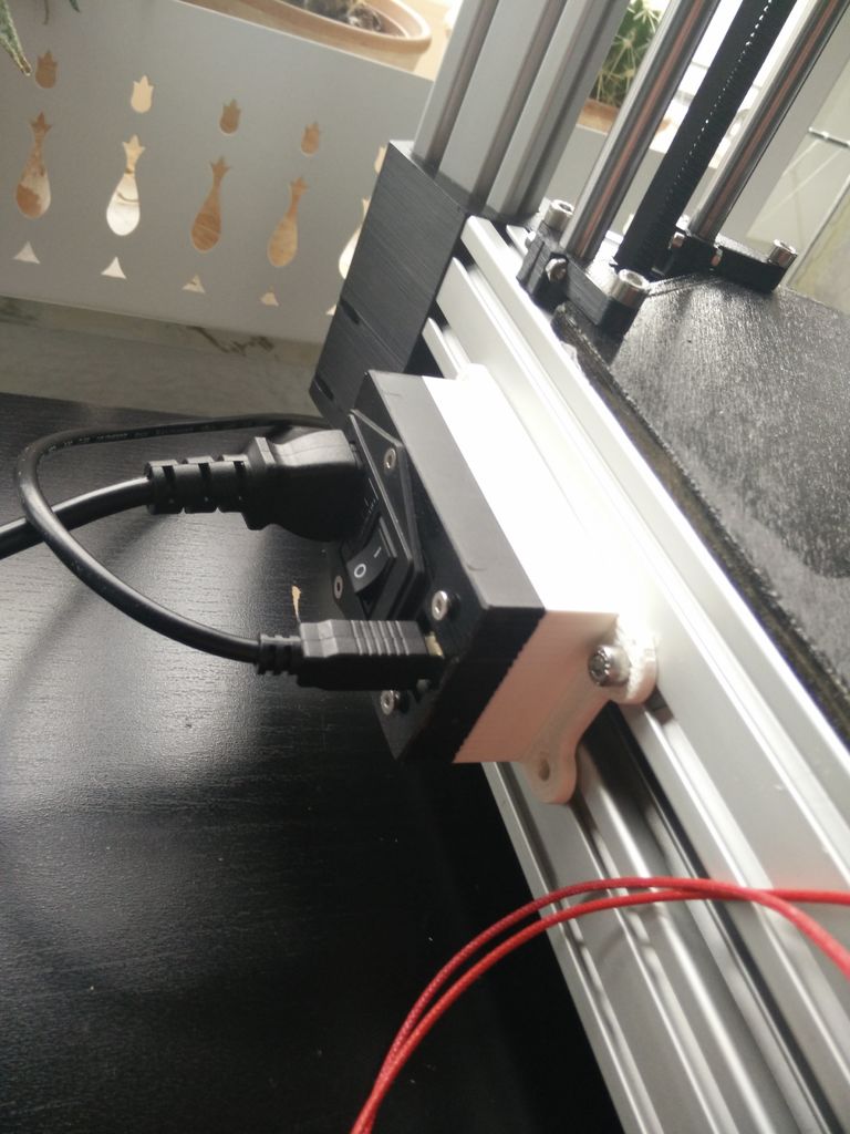
- 1x connector for mains power (Kaltgerätestecker)
- cables, connectors, general electronics stuff you’ll need
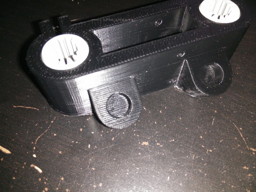
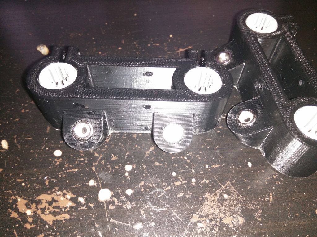
Printed parts:
- 6x delta arm carriage belt clamp
- 1x delta magnetic effector
- 1x delta magnetic effector fanduct
- 1x delta calibration tool (only if you want to use auto delta calibration in smoothieware)
- 1x delta effector clamp1
- 1x delta effector clamp2
- 12x delta rod end
- 12x delta rod holder (type a or b, see step 5)
- 3x delta top corner
- 3x delta bottom corner
- 3x delta arm carriage
- 1x delta fan holder electronics
- 6x delta feet
- 1x delta i o panel (or delta i o panel with lan — has usb and lan pass)
- 2x delta spool hanger
- 2x 000 delta axis alignment tool (optional)
Делаем Delta 3D-Printer.
Это уже второй собранный мной 3D-принтер, первый я собрал из говна и палок как говорится, со временем он сам себя проапгрейдил до вполне приличной конструкции на H-Boot кинематики.
В рамках очередного апгрейда оного на али были заказаны рельсы для переделки кинематики с валов на рельсы, и тут мне на глаза попался подходящий халявный алюминиевый профиль, к этому времени я уже более менее освоил сапр Компас, и в голове зародился проект, который в свою очередь реализовался в 3D модель, по которой и построен delta принтер.
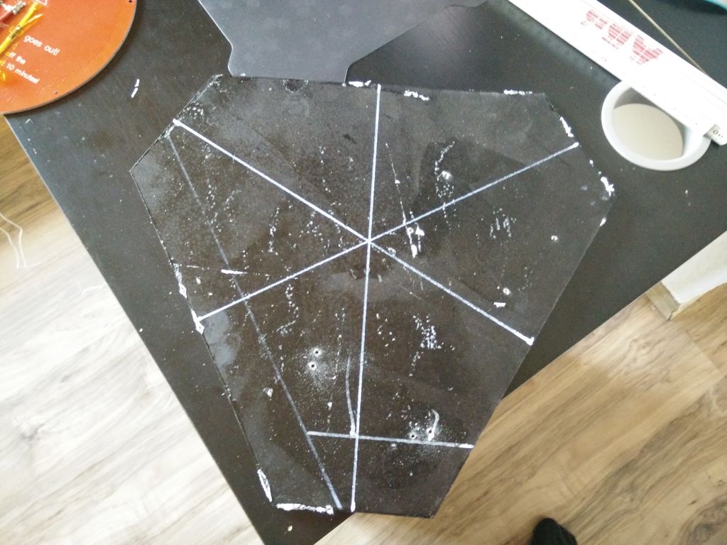
Корпус изготовлен полностью из алюминия, размер рабочей области в 260 мм «нарисовался» из наличия листа дюрали которого хватило на стол и несущую плиту, соответственно остальные размеры произвольные.
Несущие углы напилены из уголка 50 х 50 х 3 мм по распечатанным шаблонам из 3D модели.
Соединения всех элементов типа Т- болтов и гаек конструкционного профиля имеют достаточную свободу, и перед окончательной затяжкой позволяют выставить все углы и размеры.
Соответственно допускают применение «домашнего» инструмента, я обошолся пилой по металлу, напильником, и электролобзиком, ну и керосин чтоб всё это поливать при пилении, обработка алюминия на сухую это тот ещё геморой.
Из измерительного инструмента нужен хороший уголок, линейка и цифровой штангент циркуль.
Пару часов пиления, и получился набор для сборки дельта принтера !
К сожалению процесс сборки опередил процесс фотографирования, но кое что есть.
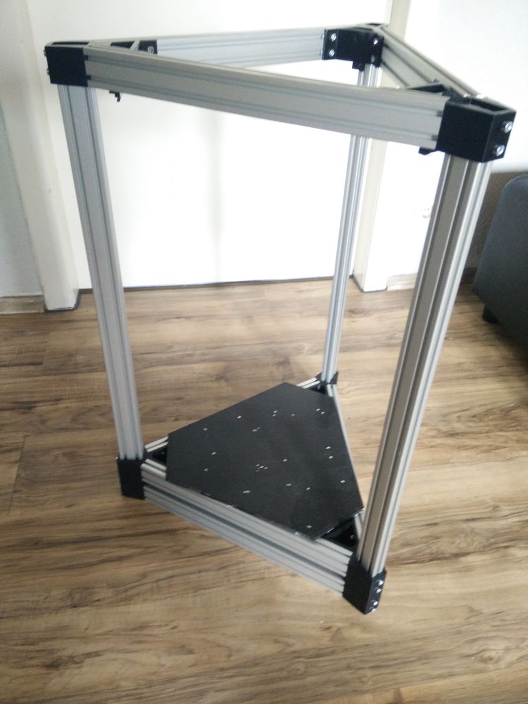
В этой конструкции нет направляющих углов, и сборка несущего каркаса требует прямых рук, зато перед окончательной затяжкой соединений всё регулируется взад и поперёк, собственно углы они уже под 90 градусов, остаётся только выставить вертикальность, и расположение башен, всё делается на ровной поверхности с помощью простого угольника.
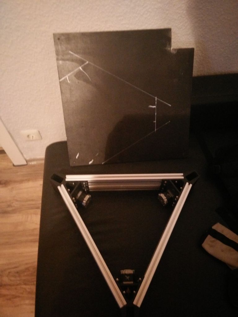
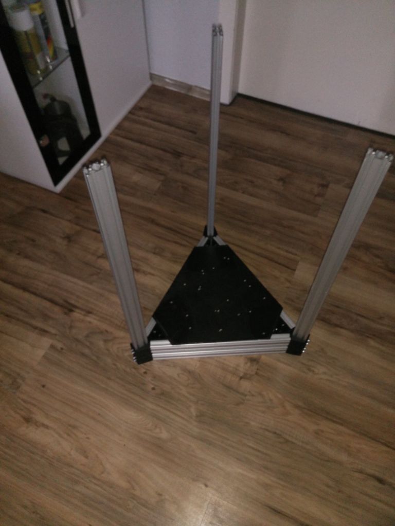
По распечатанным шаблонам (аля большие треугольники) собираем нижний и верхний треугольники.
На низ монтируется подстольник (он же силовая часть рамы), стол, ну и втыкаем башни пока незатягивая.
Для удобства установки башен относительно друг друга использовал вот этот шаблон с thingiverse очень удобно, вертикальность выставляем угольником.
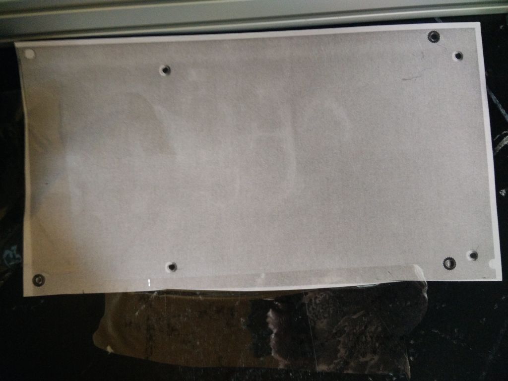
После затяжки болтов ложим на стол лист бумаги так что бы он не елозил, и поочерёдно прикладывая линейку к двум башням рисуем треугольник, далее внутри треугольника чертим медианы которые при правильном расположении башен должны пересекаться в одной точке, добиваемся идеального совпадения иначе принтер будет печатать кривые модели.
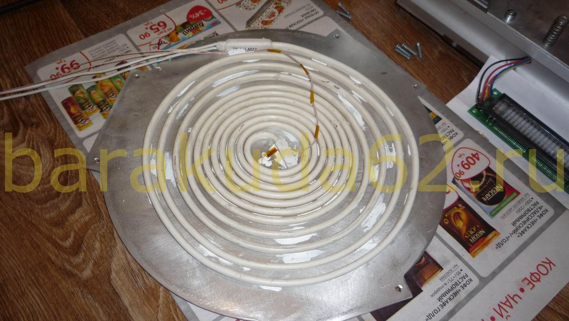
Стол с подогревом на 220v, в поднебесной такого размера столы (265мм) на 12v что не есть гуд из соображений энергопотребления, покупать силиконовую грелку жаба невелит, изначально преследовалась цель разгрузить силовую часть, используемый тут Б.П на 12v 5,5а чего вполне хватает моторам и электронике принтера да и друг другу они не мешают, поэтому стол самодельный.
 |
 |
 |
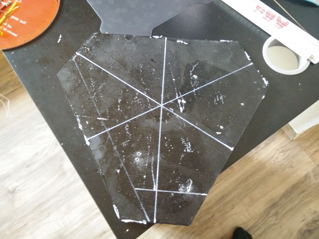
В качестве нагревателя силиконовый тен, много где используется от подогрева колонок в зимнее время, до обогрева слива морозильных камер, мне достался от знакомого холодильщика, бывают они разные по длинне и мощности мной испытано два варианта на 30 и 40w на метр диной в 5 метров, оба варианта справляются со своей задачей нагрева стола до 110 градусов примерно за 5 мин, греет и дальше но кто жеш ему даст.
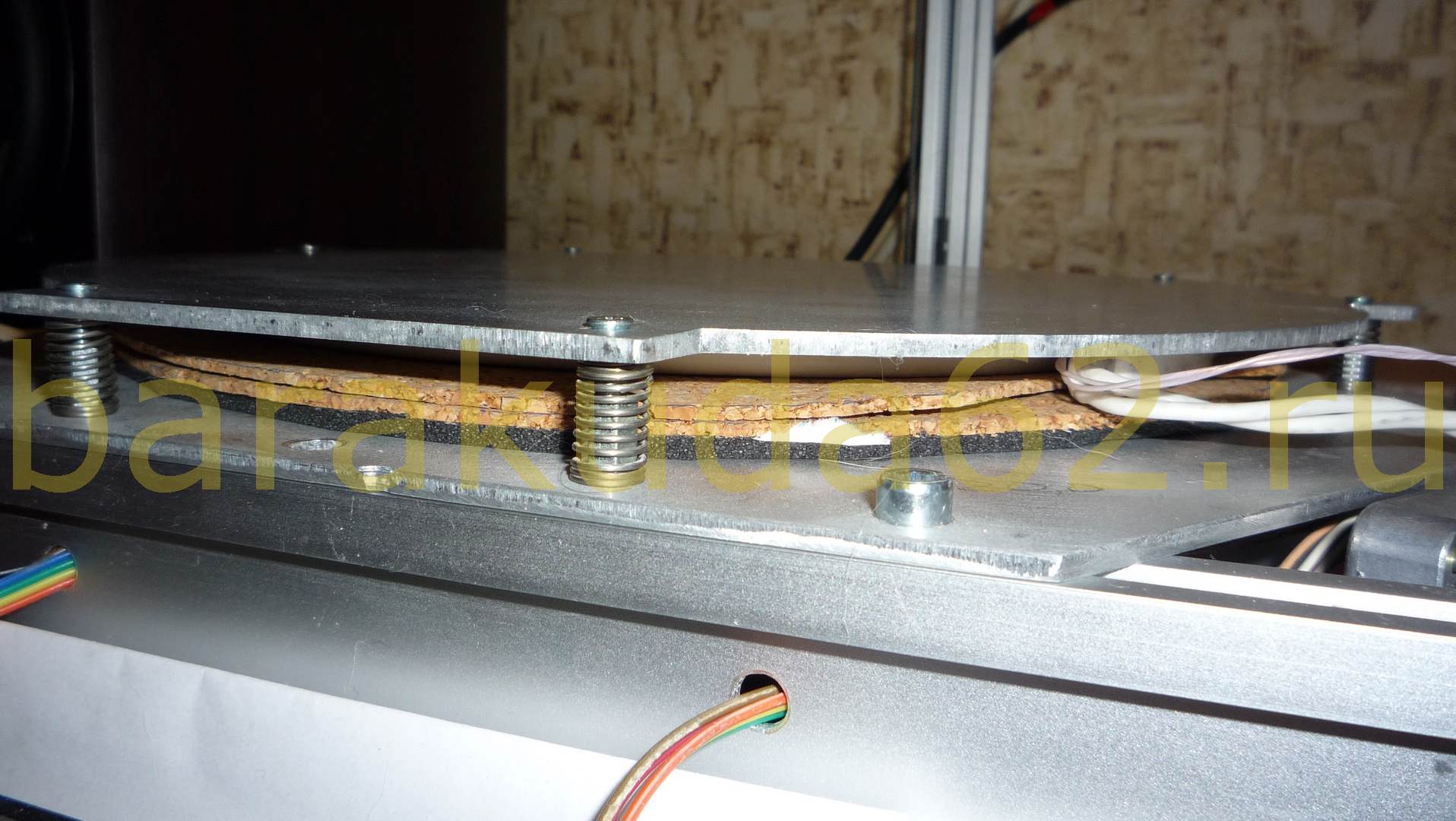
Приклеено это добро к столу из 3мм дюрали клеем Радиал местами и немного на всё про всё тюбик клей блин дорогой, вся конструкция лежит на пироге из тонкой микропористой резины для пущего прижима, и двух слоёв пробки для теплоизоляции
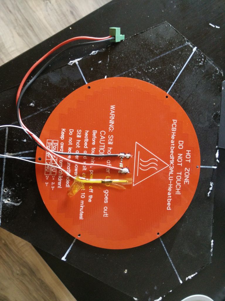
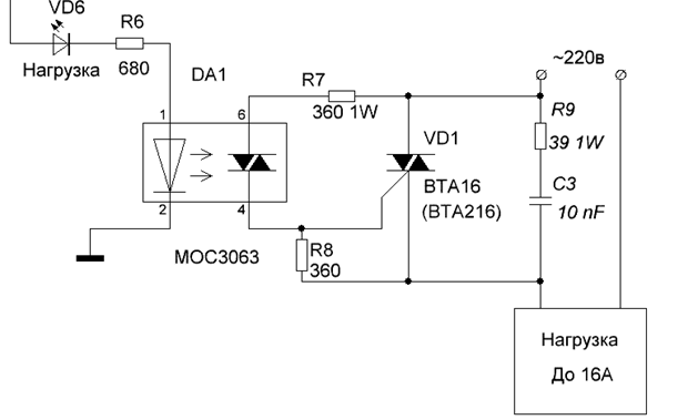
Плата питания с опторазвязкой на симисторе в силовой части, допускает использование PID контроллера, управляется с выхода ramps для подключения стола без каких либо переделок.
 |
 |
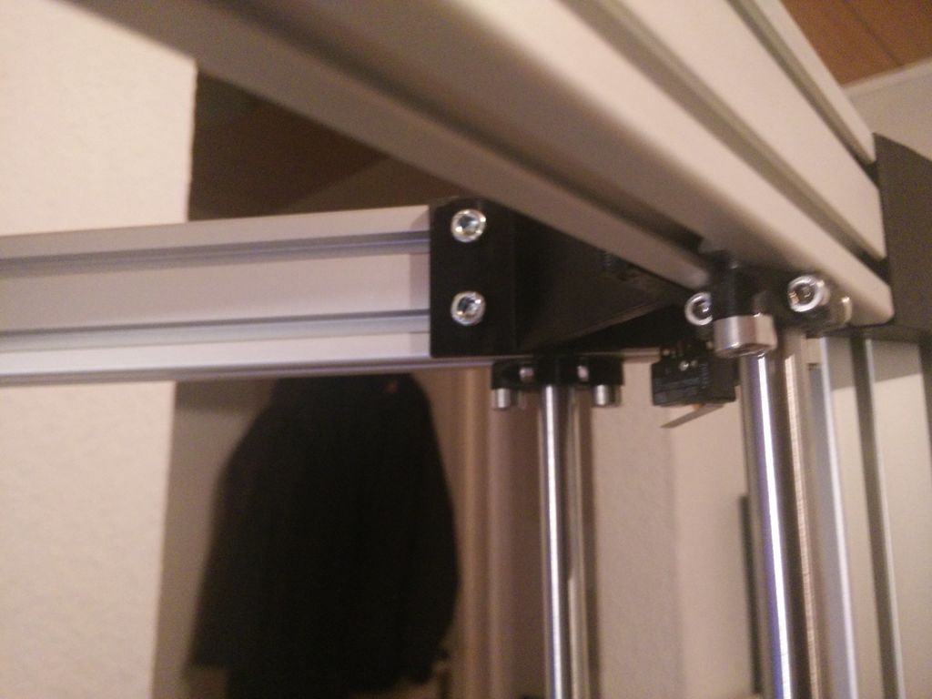
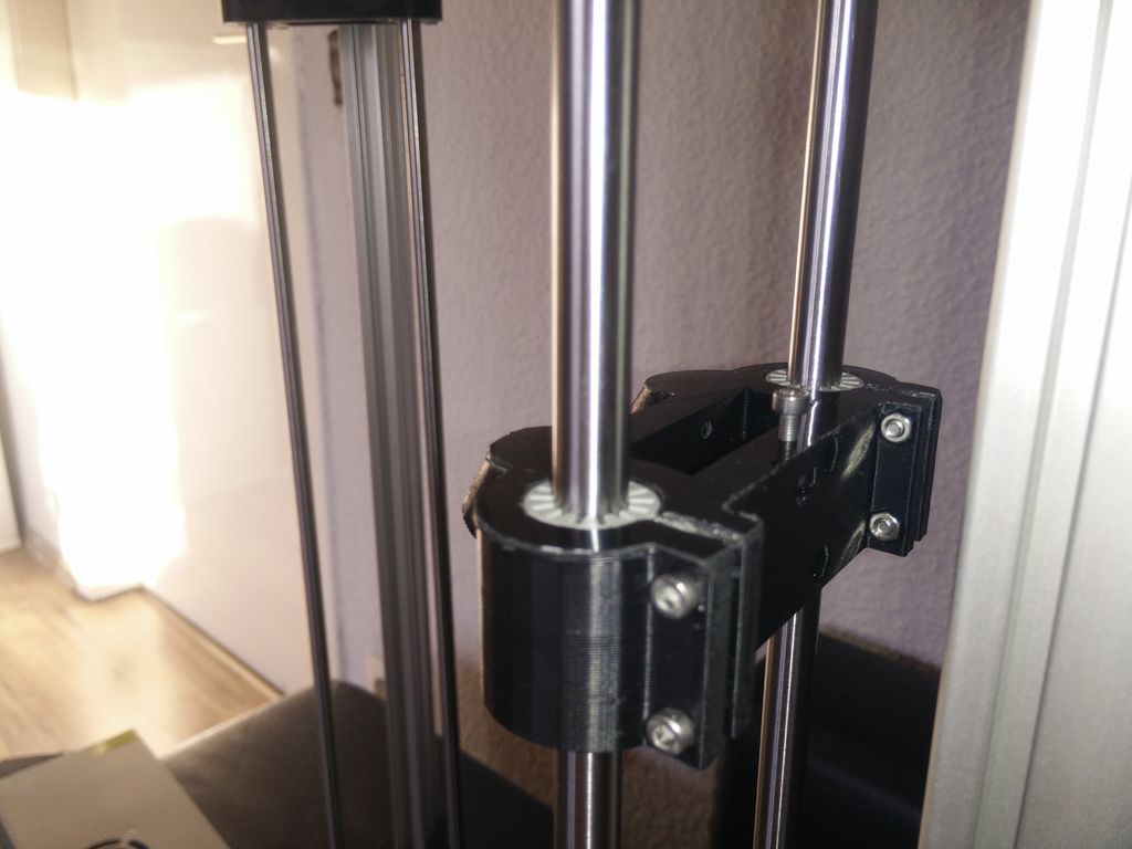
Step 5 Final Frame Assembly and Linear Motion


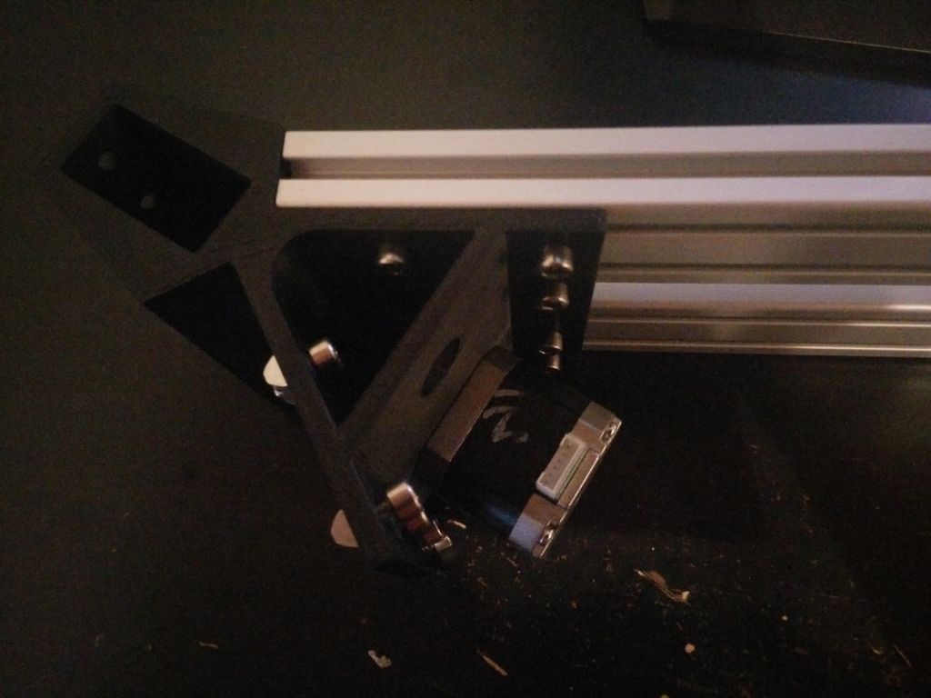
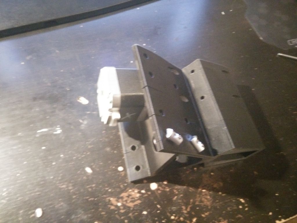
Before you assemble of your frame you have to install the linear motion system. To do so, you’ll need following printed parts: arm carriage (x3), arm carriage belt clamp (x6), holder (x12). Also you’ll need your 10 mm steel rod, the IGUS-bearings, 12 x M3x12mm screws, 6 x M3x30mm screws,18 M3 hex nuts, 12 M5 T-Nuts and 12 x M5x12mm screws.
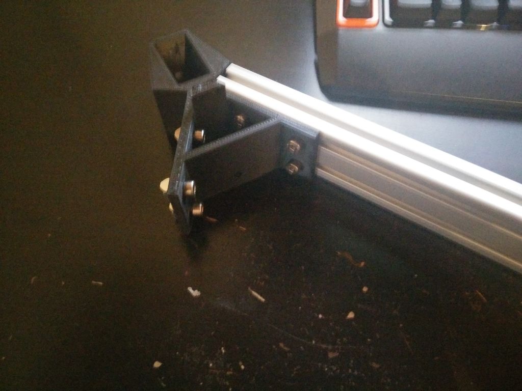
First you have to pre-assemble the frame. Just put and screw in (tight) the 4020 aluminium extrusion for the vertical struts into the bottom corner parts. Then put the upper frame on top — don’t screw this one tight right now! You have to wait until you installed the steel rods for your linear motion!
Now you have to assemble the carriage. Put the IGUS bearings into the printed part and secure them using 4 M3x14 screws and 4 M3 hex nuts (per carriage). Then install the belt holder using 2 M3 hex nuts and 2 M3x30 mm screws. finally you can insert the last M3 hex nut and the M3x20 screw for leveling — make sure to screw it only half way in so you can compensate in both directions. At last, glue in the magnets using super glue — each hole needs 2 magnets, one «normal» and one with the sunk hole.
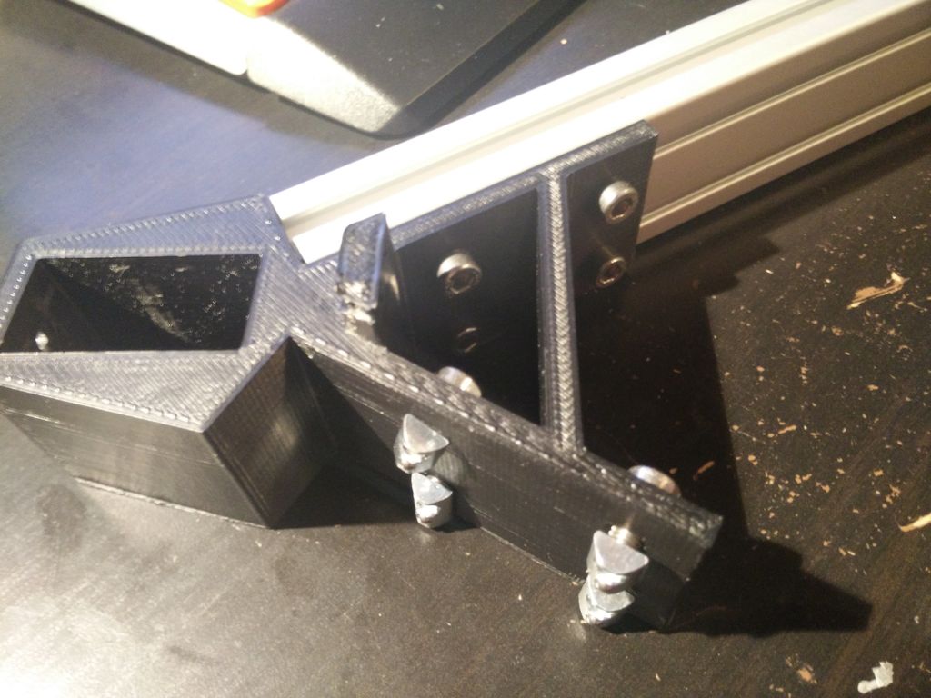
To align the rods correctly use the simple axis alignment tool. Try aligning the axis with the plate for the electronics / PSU on the printer, it may be possible that you have to (a) trim off a part of the plate to make place for the rods or (b) mount the axis partially on the plate. For this reason there is a holder / mount for the rod for Version (a) and (b). Version (b) accounts for a 6mm thick plate. Be aware that you have to use version (a) for the upper frame — because there is no plate.
Before you finally assemble / screw in the rods make sure, the plate for electronics / PSU is centred on the frame and draw out some mounting holes (I used 3 per side). Now you can lay the plate on the lower frame — while assembling the frame, mark out spots for the mounting holes. Then slide the assembled carriage onto the rods and clamp the holders on the ends of the rod using M3x12 screws and M3 hex nuts. Now you can finally install the linear motion system. Put the carriage on the rods, then clamp both sides with the respective holder. Install the part which goes to the upper partition of the frame first. For a first alignment (if you dont want to use the alignment tool) a distance of around 51-52 mm between the rod an the first slot of the aluminium extrusion (see picture) is ok.
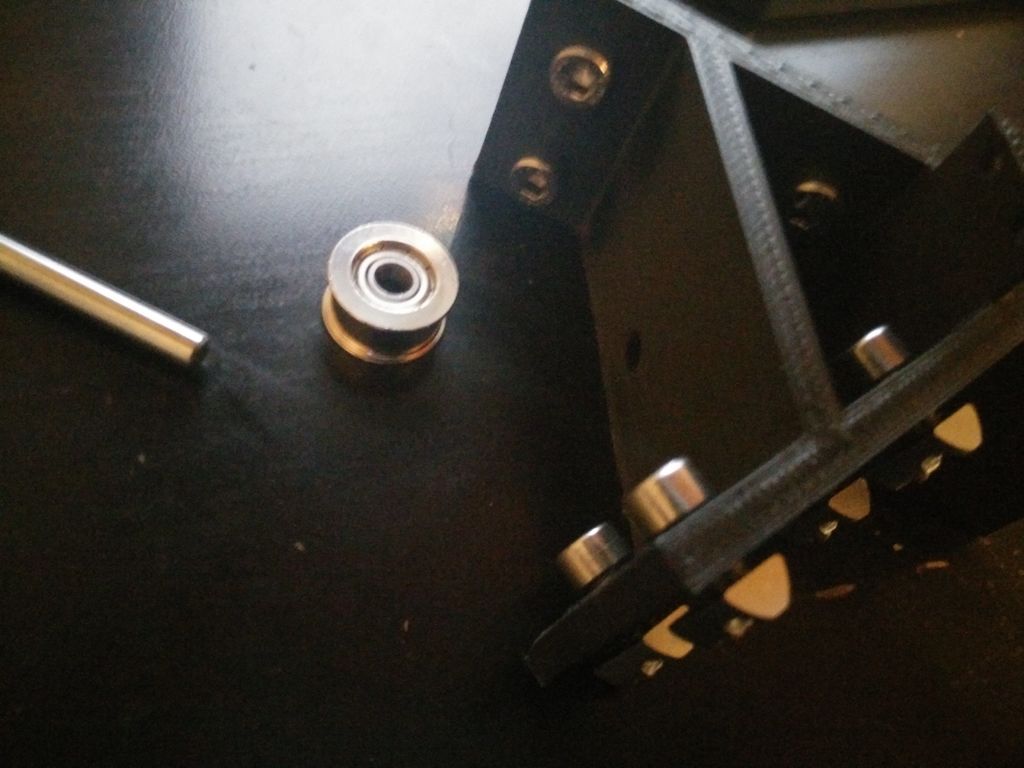
At last you can install the deflection pulley for the GT2 belts. First slide the 5x38mm stell rod into the hole in the bottom corner parts (but not completly through). Then put on the printed part named «spacer», then the deflection pulley and at last the 5mm collar («Stellring»). After that push the 5mm rod through and screw down the collar. Make shure nothing binds or rubs.
While assembling the linear motion system you have to note multiple things. First you have to measure the distance between top and bottom frame on each steel rod — they should be about the same. Make sure, the steel rods are perfectly parallel. To do so, loosly tighten the M5 screws for the clamps on the frame, move the carriage up and down severeal times and use the alignment tool to check, if everything fits. If it does and the distance between lower and upper frame parts is nearly identical screw down the steel rods on lower and upper frame. Double checke the distance afterwards! Then you can lastly tighten the screws securing the upper frame to the vertical 4020 aluminium extrusion.
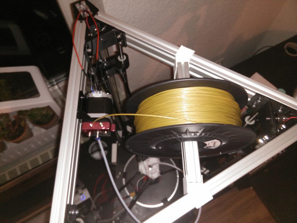
You can insert the spool holder / hanger now, but you don’t need to.
The main frame is completly assembled now.
Step 2 Pre-Build Preperation
Prepare all the tools you’ll need for assembly. I only used some screw-drivers and allen wrenches. Be careful when you assemble your electronics to not damage them or probably hurt / kill yourself. Be especially careful when wiring mains power.
Printed parts preparation
First you have to print all the parts listed before — obviously. I designed them to print without support. Maybe you have to use a raft, depending on the machine you print them on — I did all my parts with 25% triangular infill.
Check all holes before starting to assemble. Sometimes holes come out smaller then you want them to be — I checked the tolerances of the parts for the printers with publicly available files on different 3D-file-repositories to make sure, the tolerances fit — but your mileage may vary.